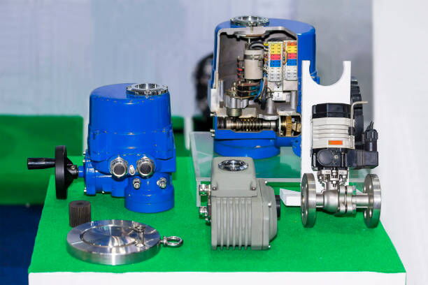
In modern industrial production, control valves play a critical role in regulating flow, pressure, and temperature across a variety of systems. However, prolonged usage without maintenance or recalibration can lead to significant deviations in valve stroke accuracy. This issue—where the valve fails to open to the exact required position—can severely impact system performance, efficiency, and safety.

The "stroke" of a control valve refers to the range of motion the valve plug or disc travels as it opens or closes. This stroke is typically measured from 0% (fully closed) to 100% (fully open). Over time, mechanical wear, vibration, pressure fluctuations, and environmental conditions can cause discrepancies between the control signal and the actual valve position. In simpler terms, when an operator or control system attempts to open the valve to a specific percentage—say 25% or 75%—the actual opening may differ significantly, leading to process instability.
To correct such errors, routine calibration and adjustment are essential, especially in systems where precision is vital.
During calibration, technicians typically select five key points across the stroke range to verify and fine-tune the valve’s responsiveness. These reference points—0%, 25%, 50%, 75%, and 100%—help ensure linearity and consistency throughout the valve's operation.
The adjustment process is especially crucial for mechanical valve positioners, which rely on manual components to fine-tune the valve's response to control signals. Proper calibration involves identifying two critical manual adjustment mechanisms inside the valve positioner: one for zero position and one for span.
Let’s explore how this adjustment is done using an "air-to-open" control valve as an example.
The first step involves sending a 4 mA signal from the control room or a signal generator. For an air-to-open valve, this signal should fully close the valve. If the valve remains even partially open, a zero point adjustment is required. This involves manually adjusting the internal mechanism until the valve is completely closed at 4 mA.
Next, a 12 mA signal is sent to target a 50% valve opening. If the valve does not respond accurately, span adjustment is needed. During this step, technicians must ensure that the feedback linkage between the valve stem and the positioner rod is in a vertical alignment to avoid introducing mechanical bias.
Once mid-point calibration is complete, a 20 mA signal is used to verify full opening at 100%. Any deviation at this point must be corrected by revisiting the span or mechanical alignment.
After adjustments at the three primary points—0%, 50%, and 100%—the technician should verify positions at 25% and 75% to ensure the valve opens proportionally across the full stroke. Multiple iterations may be necessary to refine the settings for optimal performance.
Control valve technology has evolved significantly with the rise of intelligent positioners. Unlike their mechanical predecessors, intelligent valve positioners come equipped with microprocessors, digital signal processing, and auto-calibration features. These enhancements simplify installation, reduce maintenance time, and improve overall accuracy.
Mechanical valve positioners are still widely used, particularly in harsh industrial environments or facilities with budget constraints. These devices provide direct feedback from the valve stem and rely on spring and cam mechanisms to adjust the valve position. Calibration and maintenance require a hands-on approach, involving disassembly, manual tuning, and real-time testing.
For new instrumentation technicians or engineers, mechanical positioners serve as an excellent training ground. Working with them helps build a solid understanding of valve dynamics and internal mechanisms, promoting better troubleshooting skills and a deeper comprehension of process control systems.
On the other hand, intelligent valve positioners greatly reduce the labor intensity for frontline maintenance personnel. They automatically recognize stroke limits, adjust zero and span settings, and offer diagnostic capabilities. With digital displays and user-friendly interfaces, most tasks are reduced to reading the manual, entering configuration menus, and pushing a few buttons.
Despite their convenience, intelligent valve positioners do not eliminate the need for technical expertise. Operators still need to interpret calibration data, evaluate performance trends, and respond to alarms or faults. However, the burden of manual calibration is dramatically reduced, increasing overall system reliability and uptime.
Whether mechanical or intelligent, valve positioners play a dominant role in any automated process control system. They act as the critical link between the control signal (typically a 4-20 mA current loop) and the physical motion of the valve. Without a functioning positioner, the system cannot interpret or act on control commands accurately.
If a positioner fails—due to wear, misalignment, signal interruption, or internal fault—automatic control is compromised. The system may enter manual mode, halt production, or trigger safety alarms. In high-stakes industries like oil and gas, chemical processing, or power generation, such failures can lead to costly downtime or even hazardous incidents.
For field technicians and engineers, here are a few practical recommendations to maintain valve position accuracy:
Implement a routine calibration schedule—ideally every 6 to 12 months depending on system usage and environmental factors.
Ensure the feedback rod and valve rod remain properly aligned. Misalignment can introduce non-linear behavior and increase wear.
When reinstalling components during mechanical positioner adjustments, avoid excessive tightening which can distort mechanical parts or misalign cams and springs.
For intelligent positioners, take advantage of built-in diagnostics to monitor valve health, detect sticking, or identify hysteresis.
Always log the calibration data, including the current values and valve positions. This record helps track valve performance over time and assists during troubleshooting.
The transition from mechanical to intelligent valve positioners reflects a broader trend in industrial automation: increasing efficiency while reducing manual labor. Yet, both types of positioners play indispensable roles in maintaining process accuracy, reliability, and safety.
Mechanical positioners remain invaluable tools for training and environments where digital components may be too sensitive or expensive. Meanwhile, intelligent positioners offer unmatched precision and diagnostics in critical automated systems.
Regardless of the type, a malfunctioning positioner renders any automatic control system ineffective. Thus, investing time in calibration, understanding valve mechanics, and choosing the right positioner for the application ensures that the entire control loop functions smoothly—minimizing errors, optimizing processes, and keeping production on track.
